MANUFACTURERS TECH TIP: Fundamentals of Engine Bearing Clearances
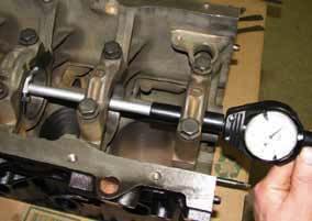
The durability of any engine – stock or performance – is tied to the engine builder’s skill in achieving optimal bearing clearances . Too little or too much clearance will reduce or eliminate the vital oil film that helps prevent contact between mating surfaces. So getting it right requires absolute precision in spec’ing and installing your replacement bearings. Bearing clearance is determined by several variables, including type and geometry of the mating parts, eccentricity, oil viscosity, oil film, shaft diameter and engine load. Mating parts: Most light-vehicle engines are assembled at the OE level by “select fitting” components to achieve tighter clearances than would typically result from random selection of mating parts, since the “stack-up” of manufacturing tolerances on the mating parts could lead to excessive NVH (Noise Vibration Harshness). The aggregate tolerance ranges for the shaft, housing and bearings equals the total possible clearance variation due to manufacturing tolerances of each mating part. Geometry: In certain respects, clearance is an important margin of safety that helps address any imperfections in component alignment and geometry. As surfaces are more precisely machined, they become less sensitive to oil film breakdown, and tighter clearances can be tolerated. Eccentricity: Half-shell rod and main bearings do not have uniform walls. Their walls are thickest at 90 degrees from the split and then drop off by a prescribed amount toward each parting line. This varying thickness is known as eccentricity, which is used to tailor the bearing shell to its rod or main housing bore that will distort under operating loads. Oil viscosity: Most new light-vehicle engines are designed to use lighter-weight oils to reduce horsepower loss. These oils can flow more freely through tighter clearances. Higher operating speeds result in considerably higher oil temperatures, therefore, and an accompanying loss of oil viscosity. Oil film: Tighter clearances help promote alignment of the shaft and bearing, which leads to a broader oil film that spreads the load over more of the bearing surface, This, in turn, improves bearing life and performance. Oil film thickness should exceed the combined roughness of the surfaces (asperities), with thickness normally ranging from .2 to 1.6 microns. Stock vs. Performance For most applications, .00075 to .0010-inch of clearance per inch of shaft diameter is a reasonable starting point. For performance engines, it’s smart to add .0005-in. clearance to the maximum determined above. This extra margin reduces sensitivity to shaft, block and connecting rod defection and the resulting misalignment that can result from peak loads. Accurate Measurement Bearing clearance is specified as “vertical clearance” and must be measured at 90 degrees to the split line. Vertical bearing clearance is best measured by assembling the bearing into its bore (at the specified torque without the shaft in place), measuring the inside diameter with a dial bore gauge, and subtracting the actual crankshaft journal diameter. Submitted by: Matt Barkhaus Sealed Power Engine Bearings Product Manager Federal-Mogul Vehicle Component Solutions OE manufacturers have components that may be graded for tolerance which they can “select” to achieve the specific clearances they desire. Since this is not a luxury afforded an automotive machine shop, it is up to the machinist to correctly adjust through machining operations housing bores and crankshaft journal sizes to achieve these desired clearances. Familiarity with the different bearing manufacturers products and their tendencies toward a thicker or thinner bearing shell and mixing bearing half-sizes are also tools you can use to achieve your clearance goals.
Engine Pro Technical Committee
March, 2014